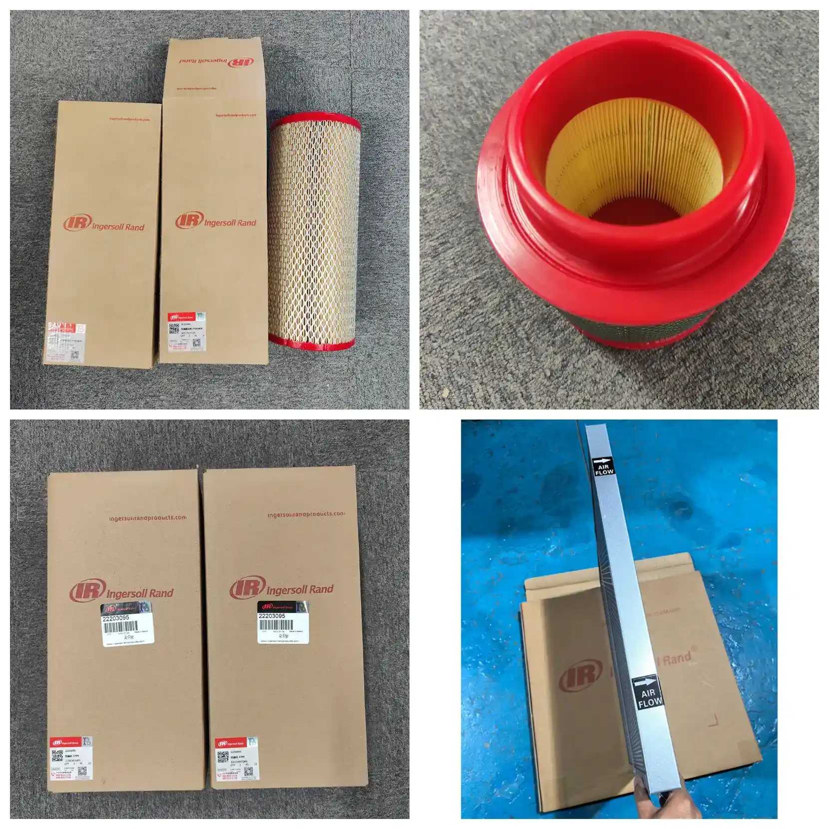
Product
Ingersoll Rand 47722477001 Air Filter Element | MSG Centac & TURBO-AIR
Ingersoll Rand 47722477001 inlet air filter element for MSG TURBO-AIR and MSG Centac centrifugal compressors. 5–10 μm filtration, ≥98% efficiency, cellulose pleated media, -10 to +80 °C. Verify by part number before ordering.
- Export packaging & documentation support
- OEM / ODM customization available
- Sample and bulk order workflow
Product Overview
47722477001 is the inlet air filter element for Ingersoll Rand centrifugal air compressors. It installs inside the intake filter assembly, upstream of the centrifugal impeller inlet. As the first barrier in the air path, it captures dust, sand and fibers before they reach the impeller and intercooler.
This part number belongs to the Ingersoll Rand centrifugal product line (CC), with item-level model code P675 and unit group designation C675. Centrifugal units are designed as 100% oil-free (ISO 8573-1 Class 0). With no lubricating oil in the compression chamber to carry contaminants away, particles deposit directly on the impeller and cooler surfaces — making inlet filtration more critical than on oil-flooded screw compressors.
| Item | Value |
|---|---|
| Part Number | 47722477001 |
| Name | Air Filter Element |
| Brand | Ingersoll Rand |
| Application | Ingersoll Rand centrifugal compressors (MSG TURBO-AIR / MSG Centac series) and packaged systems |
| Product Line | Centrifugal (CC) |
| Filtration Rating | 5–10 μm |
| Filtration Efficiency | ≥98% (for particles ≥5 μm) |
| Recommended Replacement | 2,000 hours or 3 months |
Specifications
| Parameter | Detail |
|---|---|
| Part Number | 47722477001 |
| Brand | Ingersoll Rand |
| Product Name | Air Filter Element |
| Category | Inlet filtration (air filter) |
| Product Line | Centrifugal (CC) |
| Application | Ingersoll Rand centrifugal compressors (MSG TURBO-AIR / MSG Centac series) |
| Installation Position | Inside intake filter assembly, upstream of centrifugal impeller inlet |
| Air Quality Class | 100% oil-free, ISO 8573-1 Class 0 |
| Replacement Interval | 2,000 hours or 3 months |
Fitment verification: Centrifugal units typically carry two filter elements — an inlet filter and a downstream clean filter — with different part numbers. Before ordering, confirm: (1) the stamped part number on the old element end cap or cage matches the ordered number; (2) the model and group designation on the unit nameplate; (3) the old element's installation position (inlet stage or clean stage). Ordering by unit model alone risks incorrect fitment, particularly on centrifugal machines.
Technical Data
Filtration Performance
| Parameter | Value / Notes |
|---|---|
| Filtration Rating | 5–10 μm |
| Filtration Efficiency | ≥98% (for particles ≥5 μm) |
| Filter Class | Characterized per ISO 5011 by efficiency, resistance and dust holding capacity; HVAC classification (G4/F7 etc.) does not apply |
| Dust Holding Capacity | — |
Flow and Resistance
| Parameter | Value / Notes |
|---|---|
| Rated Air Flow | Must exceed unit rated intake flow; sized after correcting for discharge volume, inlet temperature and altitude |
| Initial Pressure Drop | Approx. 0.3–0.5 kPa (clean, new element) |
| Operating Differential | Rises with dust loading; typical range approx. 0.5–1.5 kPa |
| Alarm / Final Resistance | Typical replacement threshold approx. 1.5–2.5 kPa; for centrifugal units the intake depression gauge reading is the final criterion |
| Pressure Drop vs. Energy | Each 1 kPa increase in inlet resistance raises compression ratio by approx. 1%, increasing unit energy consumption by approx. 1.0% |
Pressure drop / energy relationship (theoretical, at 0.85 MPa discharge gauge pressure):
| Inlet Resistance | Compression Ratio | Energy Increase |
|---|---|---|
| 0 kPa (new element) | 9.39 | Baseline |
| 0.5 kPa | 9.44 | +0.5% |
| 1.0 kPa | 9.49 | +1.0% |
| 1.5 kPa | 9.53 | +1.5% |
| 2.0 kPa | 9.58 | +2.0% |
| 2.5 kPa | 9.63 | +2.5% |
From installation to replacement threshold, inlet resistance rises by more than 2 kPa, increasing unit energy consumption by roughly 2%. Centrifugal units are high-power and often run continuously — the energy penalty typically exceeds the filter element price, so running past the resistance limit is not economical.
Construction and Materials
| Parameter | Value / Notes |
|---|---|
| Filter Media | Cellulose fiber paper (wood pulp), pleated construction |
| Media Weight | Approx. 130 g/m² |
| Inner / Outer Cage | Galvanized steel perforated cage, supporting media on both sides |
| End Caps | Metal or polyurethane, bonded to media |
| Seal | Polyurethane or NBR rubber, integral with or separate from end cap |
| Adhesive | Polyurethane, for media-to-end-cap and cage bonding / edge sealing |
Operating Conditions
| Parameter | Value / Notes |
|---|---|
| Operating Temperature | -10 °C to +80 °C |
| Relative Humidity | ≤90% RH (non-condensing) |
| Burst / Collapse Resistance | Standard design withstands ≥5 kPa across media without deformation |
| Function | Inlet-stage filtration for oil-free centrifugal units; works with downstream clean filter to maintain air quality |
Service Life and Maintenance
| Parameter | Value / Notes |
|---|---|
| Service Life | 2,000 hours or 3 months, whichever comes first |
| High-Dust Environment | Reduce hours accordingly (e.g. approx. 1,500 hours); shorten calendar limit as well |
| Shelf Life | Use within 24 months; store dry, ventilated, away from light; avoid moisture and compression deformation |
| Replacement Criteria | Intake depression gauge reading exceeds limit, or media shows damage, debonding, or compressed seal face |
Standards
| Standard | Notes |
|---|---|
| ISO 5011 | Test method for inlet filter efficiency and dust holding capacity — the performance basis for this class of air filter |
| ISO 8573-1 | Compressed air quality classes; units in this class are Class 0 (100% oil-free) |
| Note | ISO 2941 / 2942 / 2943 / 3723 / 3724 series commonly cited in replacement-part literature are hydraulic filter standards for pressure, burst and filtration characteristics — not applicable to air filters and should not be used as air filter performance criteria |
Installation and Maintenance Steps
Step 1 — Confirm unit status and spare part. Check the unit nameplate model and group designation; confirm the ordered element matches the old part number. Prepare the new element, clean cloths and necessary tools.
Step 2 — Shut down, depressurize, disconnect power. Follow the shutdown procedure, wait for full depressurization (centrifugal units have rotational inertia — wait for the controller to confirm zero speed). Lock out and tag out the main power. This step is mandatory.
Step 3 — Verify the old element before disassembly. Before opening the intake filter assembly, read the stamped part number and note the installation position on the old element; confirm it matches the ordered part. Inlet-stage and clean-stage elements on centrifugal units have different part numbers — this is the key error-prevention step.
Step 4 — Remove and inspect the old element. Lift out vertically and inspect dust distribution and media condition. Replace immediately if media shows damage, perforation, end-cap debonding or compressed seal face, even if the interval has not elapsed. Black oily sludge on the outer surface indicates abnormal oil mist in the intake — investigate upstream conditions (particularly relevant on oil-free units).
Step 5 — Clean the assembly interior. Wipe the inner walls and base with a lint-free cloth. Do not blow compressed air directly into the assembly (it drives dust into the intake path). Criterion: no loose dust on inner walls, seal face flat and free of debris.
Step 6 — Install the new element. Fit in the same orientation and position as the old element, noting seal face direction and clamping method. Criterion: element seats without movement, seal face evenly compressed around its circumference.
Step 7 — Reassemble and confirm sealing. Refit the cover or clamp and tighten evenly per unit requirements. Check that the intake depression gauge impulse line is clear — a blocked line gives a false "clean" reading and is a common source of misjudgment.
Step 8 — Reset, test run, record. Reset the maintenance timer, start the unit at no load, and observe the depression gauge reading and running sound. Criterion: gauge stable within the unit's allowable range, no abnormal whistling (whistling often indicates seal bypass). Record the unit running hours at replacement as the starting point for the next interval.
Frequently Asked Questions
Q1: Which units use 47722477001?
Ingersoll Rand centrifugal air compressors — MSG TURBO-AIR and MSG Centac series and their packaged systems (item-level model code P675, unit group designation C675). Centrifugal units are 100% oil-free by design. For a specific unit, confirm against the nameplate and old element part number.
Q2: Can it be used on an oil-flooded screw compressor?
Not recommended. This element belongs to the centrifugal product line; its dimensions and interface are designed for centrifugal intake assemblies. Oil-flooded screw compressors use a different part number system, and cross-use cannot guarantee sealing or filtration performance.
Q3: What is the replacement interval?
The standard interval is 2,000 hours or 3 months, whichever comes first. In high-dust environments (cement, quarrying, mining, metalworking), reduce to approximately 1,500 hours. The intake depression gauge reading is the final criterion — replace when the reading exceeds the limit, regardless of running hours.
Q4: Why is inlet filtration more demanding on centrifugal units than screw units?
Centrifugal units are oil-free; with no lubricating oil in the compression chamber to carry contaminants away, particles deposit on the high-speed impeller and intercooler surfaces. Impeller fouling causes dynamic imbalance and requires shutdown for rotor correction. Screw units have an oil film that partially carries contaminants away, giving more tolerance in inlet filtration.
Q5: Why are dimensions not listed?
Centrifugal units are supplied as project-based packages; intake assembly dimensions vary between group designations and package scopes within the same series, so listing a single dimension would be misleading. We recommend measuring the old element's outer diameter, inner diameter, overall height and seal type, or providing photos of the old element and unit nameplate so we can cross-reference by part number.
Q6: What are the consequences of rising inlet resistance?
First, energy consumption rises — each 1 kPa increase in inlet resistance raises compression ratio by approximately 1%, increasing unit energy consumption by approximately 1%. Second, intake volume drops, reducing unit discharge. Continuing past the replacement threshold costs more in electricity than the filter element itself.
Q7: Can alternative parts be used?
Yes, but verify three items: filtration rating, end-cap seal type, and dimensions. If an alternative's seal type does not match the original, bypass occurs — on an oil-free centrifugal unit, bypass means particles reach the impeller directly, a higher risk than on oil-flooded units. When sourcing alternatives, provide old element photos and this part number.
Q8: What should I do if abnormal whistling occurs after installation?
Whistling typically indicates seal bypass — the element is not fully seated, the seal face is deformed, or the seal is missing. Shut down immediately and recheck: is the element seated, is the seal face compressed or inverted? Also check whether the intake depression gauge impulse line is blocked to avoid misdiagnosis.
Q9: What are the storage requirements?
Store in a dry, ventilated, dark location; protect from moisture, rain and heavy compression. Moisture reduces media strength; compression deformation damages the seal fit. Use within 24 months.
Q10: Which other filters in the same series are easily confused?
In the Ingersoll Rand centrifugal product line, a single unit often carries both an inlet filter and a downstream clean filter, with different part numbers and installation positions. Before ordering, confirm whether it is the inlet stage or clean stage — filtration rating, materials and seal type differ between the two.
Compatible Models
This part is designed for Ingersoll Rand centrifugal air compressors:
| Item | Detail |
|---|---|
| Unit Type | Centrifugal air compressor |
| Product Line | Ingersoll Rand centrifugal product line (CC) |
| Series | MSG TURBO-AIR / MSG Centac |
| Item-Level Model Code | P675 |
| Unit Group Designation | C675 |
| Air Quality Class | 100% oil-free, ISO 8573-1 Class 0 |
| Typical Applications | Continuous, clean, oil-free air supply (food and beverage, pharmaceutical, electronics, textile, pneumatic conveying, etc.) |
Representative model families (family-level reference; individual fitment must be verified by serial number):
| Series | Representative Models |
|---|---|
| MSG TURBO-AIR | TA / NX series packaged units |
| MSG Centac standard pressure | C series (C400, C700, C800, C1000, C3000, etc.) |
| MSG Centac high pressure | C750, C1050, 2CII, 3C, 4C and other high-pressure units |
| Packaged systems | Refrigerated dryers, filters, air receivers and other downstream equipment for the above units |
Why verification by part number, not unit model: Centrifugal units are supplied as project-based packages — intake assembly configuration, downstream scope and interface dimensions can differ between projects for the same unit model. A single unit also carries both inlet-stage and downstream clean-stage elements with different part numbers. Therefore, select parts based first on the old element's stamped part number, second on the unit nameplate, and third on the installation position.
Three-step verification:
- Read the stamped part number on the old element end cap or cage and compare with the ordered number.
- Read the model and group designation on the unit nameplate and compare with the unit parts manual.
- Confirm the old element's installation position (inlet stage / clean stage) — the two are not interchangeable.
If verification is still inconclusive, provide a photo of the unit nameplate, a photo of the old element (including stamped part number) and the installation position; we will cross-reference by part number and confirm.
Cross-series note: Centrifugal unit filter elements and oil-flooded screw compressor elements belong to different part number systems and are not interchangeable. Screw compressor air filter dimensions and interfaces are designed for external intake assemblies; direct substitution will cause seal failure.
Related Components
In the Ingersoll Rand centrifugal product line's intake and air path system, the following components are serviced on the same cycle or in the same section:
| Component | Part Number | Function | Inspection Points |
|---|---|---|---|
| Sterile filter element | 47722478001 | Downstream sterile-grade filter, further removing microorganisms and particles from compressed air for higher-purity applications | Belongs to a different filtration stage from the inlet filter; part numbers are not interchangeable. Confirm installation position at replacement. |
| Air filter assembly (housing) | — | Housing assembly that holds and secures the inlet filter element | Check clamps, seal faces and outlet end for deformation or corrosion |
| Intake depression / differential gauge | — | Displays inlet resistance; the final criterion for replacement interval | Periodically check the impulse line for blockage — blockage gives a false "clean" reading |
| Seals | — | Prevent bypass between element and assembly | Inspect together with the element; replace if compressed, hardened or missing |
| Unit lubricating oil and oil filter | — | For the centrifugal unit's gearbox and bearing lubrication system (not compression chamber oil) | Replace per the unit parts manual interval; inspect together with the inlet filter |
Recommended replacement practice: Inspect the inlet filter, downstream clean filter and seals together, deciding each on its own criteria. The inlet filter and downstream clean filter have different replacement intervals (the downstream element is typically judged by cleanliness requirements rather than dust loading), so synchronized replacement is not required.
For specific part numbers: Items marked "—" above should be confirmed against the unit-specific parts manual — centrifugal units are project-based packages, and the manual lists companion part numbers corresponding to the applied unit's serial number; they should not be applied across projects.